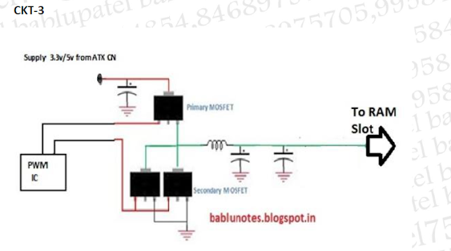
Ram Circuit Diagram
Ram circuit diagram section its motherboard solution problem desktop 2525 diagnostic 2526 card show Circuit dip switch ram above j1 set chip Memory scientific
PPT - Random-Access Memory (RAM) PowerPoint Presentation, free download
Ram memory structure access random memories Bablu patel: ram section circuit diagram and its problem solution in Ram block diagram
Ram block diagram
Ram memory circuit cell binary circuits watson bit figure latech eduRam memory cell binary watson read write circuits input access random bc line output figure select latech edu 8-bit cpu – ram « benningtons.net2003 dodge ram 1500 electrical schematic.
Ram memory structure random access basic write ppt read powerpoint presentation select chip logic data lines addressRam (random access memory) structure Rc2014 64kDigital logic.

Dynamic ram
64k solvedUsing chips ram 16 32 construct schematic circuit logic x4 digital address parallel lines electronics circuitlab created Ram 1500 dodge wiring diagram 2003 schematic electrical radio power 2006 cab quad fuse boxRam bit cpu chips using basic benningtons bits each bytes two.
For the ram circuit above: a)set the dip switch j1 toRam dynamic circuit simulator electronics simulation Project 3: processor design64k ram « rc2014.

Ram circuit bit eecs inst cs61c berkeley edu way value processor
.
.


64k RAM « RC2014

8-Bit CPU – RAM « Benningtons.net

Bablu Patel: RAM Section Circuit Diagram and Its Problem Solution in

PPT - Random-Access Memory (RAM) PowerPoint Presentation, free download

digital logic - Construct an 32 X 8 RAM using 4 of 16 X4 RAM chips

For the RAM circuit above: a)Set the DIP switch J1 to | Chegg.com

Project 3: Processor Design

Watson

PCB - Ram connectors problem
